Wind Shear and Civil Aviation Safety - LiDAR That Improves Civil Aviation Safety
Wind shear is an atmospheric phenomenon that is a sudden change in wind speed in the horizontal and vertical directions. Wind shear, especially low-altitude wind shear, is a major factor in many aviation accidents, particularly those involving aircraft. Until recent decades, little was known about its effect on aviation safety, but recent advances in LiDAR technology have helped to improve our understanding of the effects of wind shear. Today, onboard LiDAR is often used to monitor the wind in flight, while the ground-based doppler 3D scanning wind LiDAR can detect changes in wind speed near the airport.
Wind shear is extremely harmful to aviation flight, especially during takeoff and landing, due to the low flight speed, wind shear can have a great effect on the airspeed of the aircraft, resulting in sudden changes in the aircraft’s attitude and altitude, sometimes with disastrous results at low altitudes. In 1985, a plane crashed at Dallas-Fox Airport in the United States, killed 137 people. Since then, wind shear has been studied as an international topic. According to Coleman, director of the National Center for Atmospheric Research in Boulder, after 1985, all aircraft in the United States have been equipped with wind shear detectors, and in Canada in the 1990s.
How Does 3D Dopper Scanning Wind Lidar Detect Wind Shear?
A 3-D wind lidar image is a 3D representation of the wind field. The images are usually taken from above. Wind speeds are measured in m/s. For example, an airplane flying over a runway might experience a 14 m/s wind speed. The surface wind is light at this height and is opposite to the upper levels of the atmosphere.
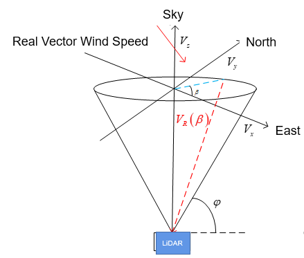
This type of wind lidar scan uses an optical head that is fixed to a fixed elevation angle. The azimuth, in turn, is constantly iterated from 0 to 360 degrees. This creates a cone surface that is displayed in 2D perspective as a circle.
A three-dimensional wind lidar image is a composite of multiple images. The data is interpreted by an expert to produce an accurate prediction for an airport’s condition. It can also be used to identify wind-related conditions. In addition to detecting wind-shear, it can also be used to identify microbursts. If a particular weather event is accompanied by strong wind, an alert is generated.
Using this technology, lidar can detect severe weather phenomena that can affect aviation. For example, low-level wind shear is often accompanied by downbursts. In order to detect wind shear, lidar data can be processed and analyzed by a computer algorithm. In addition, lidar data is evaluated for aerosol content.
Doppler 3D Scanning Wind LiDAR Glide Path Scanning Principle
Glide path scanning focuses on observing the wind field in the take-off and landing area of the aircraft, and the azimuth and pitch angles change simultaneously during the scanning process.
Use PPI mode of 3D Scanning Wind LiDAR to detect Wind Shear
PPI scanning principle: Under the condition of constant LiDAR pitch angle, azimuth angle swing scanning.
Then use the synthesized C factor to judge the wind shear:
When the C factor is between 0.068-0.138, moderate wind shear is considered;
when the C factor is between 0.139-0.206, strong wind shear is considered
when the C factor is greater than 0.207, severe wind shear is considered.
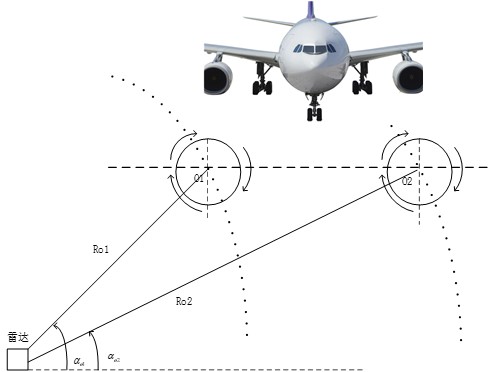
Aircraft Wake Vortex Detection
The wing of an aircraft in flight will disturb the atmosphere, forming a closed vortex that rotates in the opposite direction around the wing, which is the aircraft tail vortex. The vortex is strong and exists for a long time, which will make the flight of the following aircraft safe. It poses a serious threat, so that the follow-up distance of aircraft at the airport when taking off or landing is limited, and the airport capacity is reduced as a result.
This problem has become a key problem in the field of aircraft flight safety and airport aviation control at home and abroad. The study of wake vortex characteristics and its detection technology is of great significance to solve this problem. First, the advanced wake vortex detection technology can be used to achieve aircraft avoidance. The wake vortex can achieve the purpose of ensuring flight safety; in addition, it can break through the limitations of traditional safe flight spacing standards and greatly improve the airport transportation capacity.
Use PPI mode of 3D Scanning Wind LiDAR to detect Aircraft Wake Vortex
The principle of RHI detection of wind shear: when the azimuth angle of the radar remains unchanged, the pitch angle swing scanning.
Site Photos
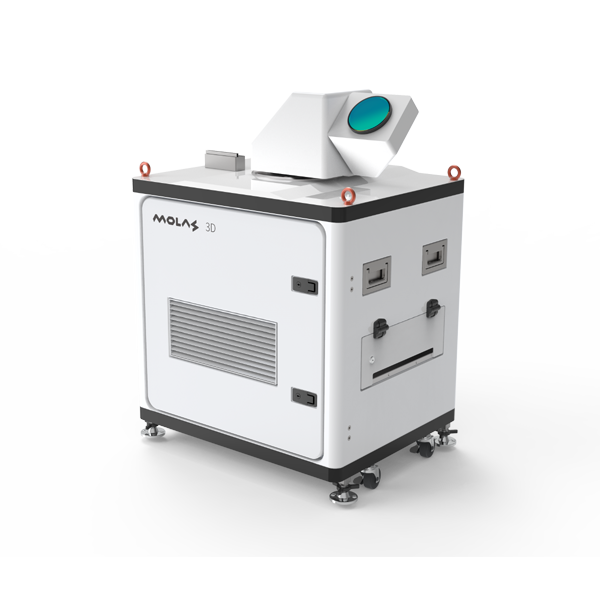
Specifications of Molas 3D Scanning Wind LiDAR
The scanning system of Molas 3D scanning wind LiDAR has strong programmability and high wind measurement accuracy, and it can be applied for wind measurements for wind projects, aircraft wake vortex and dangerous meteorological detection for civil aviation industry, high precision wind profile measurement, and emission source tracking for air quality application field.
General Specifications
Measurement Distance: 10km (Typical Situation)
Distance Resolution: 30m/45m/60m/75m Optional
Accumulation Time: 0.5s/1s/2s/4s/8s Optional
Wind Speed Measurement Accuary: 0.1m/s
Pointing Accuracy: 0.1°
Wind speed measurement range: -75m/s to 75m
Vertical Scan Range: -10°~190°
Click HERE to download the detailed specification of Molas 3D.